
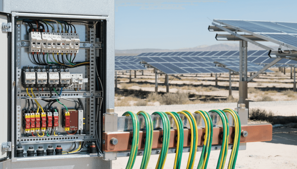
There is a fault category in industrial solar PV installations that generates more diagnostic confusion, more unnecessary maintenance interventions, and more unresolved protection relay behavior than almost any other technical issue in the DC system.
It is not a string failure. It is not an inverter fault. It is not a soiling-related performance loss.
It is an earth fault — or more precisely, what the protection system interprets as an earth fault — in the DC circuit. And in most cases, the root cause is not a genuine fault in the system. It is a DC earthing configuration that was never properly matched to the electrical characteristics of the installation, the protection scheme it connects to, or the specific environmental conditions of the MENA operating environment.
Anyone who has supervised an industrial solar installation in MENA long enough has encountered this pattern: a SEPAM residual voltage relay that trips repeatedly without a clear cause, a monitoring system that shows no string-level anomaly, an insulation resistance test that comes back within specification — and a production loss that accumulates with every unnecessary protection trip while the diagnostic team works through a fault that the original design never fully anticipated.
The financial cost of unresolved false V0 trips on an industrial solar installation is straightforward to calculate. Each unnecessary protection trip generates an inverter restart sequence of 5 to 15 minutes. At 2 to 4 trips per day on a typical affected installation, the cumulative daily production loss is 10 to 60 minutes of peak output. On an installation generating 180,000 USD per year per MWp in energy savings, the annual production loss from false V0 trips alone reaches 3,700 to 7,400 USD per MWp — before accounting for the maintenance labor, inverter stress, and diagnostic effort that each trip event generates. Over 25 years, an unresolved false V0 trip problem costs 92,500 to 185,000 USD per MWp in avoidable production losses. The IMD that would have prevented it costs approximately 2,000 to 8,000 USD installed.
This article documents the DC earthing problem that those situations almost always trace back to — the configurations available, their specific implications for MENA industrial installations, and the link between DC earthing design and the protection relay behavior that has been documented in earlier field analysis on this platform.
Disclosure: This article contains affiliate links. If you purchase through these links, I may earn a small commission at no extra cost to you. I only recommend technical resources that I consider genuinely useful for industrial solar professionals working in Africa and the MENA region.
What DC Earthing Actually Does — And Why It Matters More Than Most Designs Assume
The DC earthing system of a solar PV installation serves three distinct functions — and most design teams optimize for one of them while inadvertently compromising the other two.
Function 1 — Personnel safety
In the event of an insulation failure that creates a live voltage on an accessible conductive surface, the earthing system determines whether a person who touches that surface will be exposed to a dangerous electric shock. A properly designed earthing system limits the touch voltage and the fault current to values that are survivable — and in some configurations, ensures that the first earth fault in the DC circuit generates no significant fault current at all.
Function 2 — Equipment protection and fault detection
The earthing system is the reference against which insulation monitoring devices measure the DC circuit’s isolation from earth. The sensitivity of this measurement, the speed at which a deteriorating insulation condition is detected, and the reliability of the protection relay’s response to a genuine fault all depend directly on the earthing configuration chosen at the design stage.
Function 3 — Electromagnetic compatibility and leakage current management
In a large DC system with long cable runs — the typical configuration of an industrial C&I solar installation with an extended footprint — the distributed capacitance of the DC cables relative to earth generates leakage currents that flow continuously even when the system is perfectly healthy. The earthing configuration determines how these capacitive leakage currents are managed — whether they are absorbed harmlessly, whether they circulate through the protection scheme, or whether they are seen by the medium-voltage protection system as a ground fault signal that triggers unnecessary protection trips.
It is this third function — leakage current management — that is most consistently underestimated in the design of MENA industrial solar installations, and that is most directly responsible for the protection relay behavior that has generated field reports across the region.
The Three DC Earthing Configurations — And Their MENA Implications
Configuration 1 — Floating System (IT)
In a floating DC system, no intentional electrical connection is made between any point of the DC circuit and the protective earth conductor. The positive and negative rails of the DC circuit are both isolated from earth by the natural insulation of the cables and components.
This is the most common configuration in solar PV installations worldwide — and for good reason. Under healthy insulation conditions, a floating DC system provides the highest level of personnel safety: the first earth fault in the circuit creates no significant fault current, because there is no return path through earth.
The challenge in a MENA industrial installation with a large array footprint is what happens to the floating system under normal operating conditions. Long DC cable runs have significant distributed capacitance relative to earth. To make this concrete: a 1,000 V DC system with 3 km of total DC cable length — typical for a multi-MWp ground-mounted industrial installation in MENA — has a total capacitance relative to earth of approximately 300 to 600 nanofarads. Under normal 50 Hz AC influence from the MV transformer, this capacitance generates a capacitive leakage current of approximately 9 to 19 milliamperes. If the SEPAM V0 relay is set to a threshold of 5 to 10 mA — a common default factory setting for MV networks without a solar DC array — this normal operating leakage current will trigger the relay even when the DC insulation is perfectly healthy.
This is the mechanism that generated 2 to 4 false trips per day on the MENA installation documented in earlier analysis on this platform — not a fault, not a degraded cable, not a component failure. A healthy DC system generating capacitive leakage currents that exceeded the default V0 relay threshold.
These capacitive currents are not fault currents. They do not indicate any insulation problem. They are a normal consequence of the physics of long-cable DC systems operating at high voltage — and they will increase over time as cable insulation ages and its capacitance per meter increases.
Configuration 2 — Solidly Earthed System (TN)
In a TN-configured DC system, one conductor of the DC circuit — typically the negative rail — is intentionally connected to the protective earth at a single point, usually at the inverter DC input terminals.
This configuration eliminates the capacitive leakage current problem entirely: with a deliberate earth connection at a defined point, the zero-sequence voltage signal generated by DC capacitive currents is shunted to earth before it can reach the MV transformer. The SEPAM V0 relay sees a clean MV network.
The trade-off in a MENA industrial environment is significant. A solidly earthed DC negative rail in a location with saline soil or high soil conductivity — common in coastal industrial zones and irrigated agricultural areas across MENA — creates a direct corrosion pathway for DC structures, mounting frames, and grounding conductors. The continuous DC earth current, while small, accelerates galvanic corrosion of ferrous materials in contact with the soil at a rate that is meaningfully faster than in a floating system.
The second consequence of a TN configuration is that the first genuine earth fault in the DC positive rail — a deteriorating cable insulation, a junction box terminal that has corroded to the point of making contact with the box casing — now generates a fault current through the earth path. In a large DC system with low-impedance earth connections, this fault current can be significant enough to damage cables and components before the protection system responds.
Configuration 3 — Insulation Monitoring Device (IMD)
The most sophisticated and most appropriate configuration for large industrial C&I solar installations in MENA combines a floating DC system — retaining the personnel safety advantage of the IT configuration — with a dedicated insulation monitoring device that continuously measures the isolation resistance of the DC circuit relative to earth.
An IMD measures the DC insulation resistance between the positive and negative rails and the protective earth conductor — generating an alarm when this resistance falls below a defined threshold, typically 1 MΩ for a large system under normal operating conditions. This alarm indicates that insulation degradation is developing before it reaches the level of a genuine fault — giving the maintenance team time to locate and correct the deteriorating insulation before a protection trip occurs.
The IMD also provides a solution to the capacitive leakage current problem: properly configured, it can distinguish between capacitive leakage currents — which are frequency-dependent — and genuine resistive insulation degradation — which is DC-level. This discrimination capability eliminates the false V0 trip problem without requiring a TN earth connection that introduces corrosion risk.
For large industrial solar installations in MENA — where DC system voltages of 1,000 to 1,500 V, cable runs of hundreds of meters, and operating environments that accelerate insulation degradation combine to create exactly the conditions where insulation monitoring provides its highest value — the IMD configuration is the appropriate design choice.
The DC Earthing Decision Framework
The following diagram shows the three configurations and their specific implications for MENA industrial installations — and the mitigation pathway when the default floating configuration creates V0 relay interaction:
Flowchart DC Earthing :
flowchart LR
    A["Industrial Solar PV<br/>DC System Design<br/>MENA"] --> B{"DC Earthing<br/>Configuration<br/>Choice"}

    B -->|Option 1| C["Floating System IT<br/>No intentional earth<br/>Most common in MENA PV"]
    B -->|Option 2| D["TN System<br/>Negative conductor<br/>earth connected"]
    B -->|Option 3| E["Floating + IMD<br/>Insulation Monitoring<br/>Device continuous"]

    C --> F["Risk: Capacitive currents<br/>9 to 19 mA typical<br/>trigger false V0 trips"]
    D --> G["Risk: DC earth current<br/>accelerates corrosion<br/>in saline MENA soil"]
    E --> H["Best practice: Early warning<br/>before fault develops<br/>no false V0 trips"]

    F --> I["Mitigation<br/>Required"]
    G --> I

    H --> J["Baseline insulation<br/>documented<br/>at commissioning"]

    I --> K["Adjust V0 threshold<br/>above measured leakage<br/>Add IMD - Annual IR test"]

    K --> L["Protection Scheme<br/>Optimized"]
    J --> L

    style C fill:#ffd93d,color:#000
    style D fill:#fd7e14,color:#fff
    style E fill:#1e88e5,color:#fff
    style F fill:#ff6b6b,color:#fff
    style G fill:#ff6b6b,color:#fff
    style H fill:#61cf66,color:#fff
Legend: 🟡 Yellow = floating system — most common in MENA | 🟠 Orange = TN system — corrosion risk | 🟢 Green = IMD — recommended for large C&I | 🔴 Red = risks requiring mitigation | 🟢 Dark green = optimized protection
Why MENA Industrial Sites Create Specific Earthing Challenges
The DC earthing challenges documented across industrial solar installations in MENA are not generic solar PV problems — they are specific consequences of the MENA operating environment applied to DC systems that were often designed with default assumptions that do not reflect these conditions.
Challenge 1 — Cable insulation degradation under MENA thermal cycling
DC cable insulation in a MENA industrial installation undergoes thermal cycling of 25°C to 40°C per day — repeated daily for 25 years. This cycling progressively degrades the molecular structure of polymer insulation materials, reducing their resistivity and increasing the capacitive leakage current per meter of cable length.
The following curve shows how DC insulation resistance declines over a 25-year project lifetime under three management scenarios. The critical observation is not the endpoint value — it is the trajectory. The unmanaged scenario crosses the V0 relay interaction threshold silently, without any alarm, because the degradation is gradual enough to stay below the monitoring threshold of standard monitoring systems until the leakage current has already begun triggering false trips.
DC Insulation Resistance Decline Curve :
xychart-beta
    title "DC Insulation Resistance Decline Over 25 Years - MENA Industrial Site (MΩ per string)"
    x-axis ["Y1", "Y3", "Y5", "Y7", "Y10", "Y13", "Y15", "Y17", "Y20", "Y23", "Y25"]
    y-axis 0 --> 120
    line [100, 85, 72, 61, 48, 38, 32, 27, 20, 15, 12]
    line [100, 90, 82, 74, 63, 54, 48, 43, 36, 30, 26]
    line [100, 95, 90, 85, 78, 71, 67, 63, 56, 51, 47]
Legend: Top Curve — Floating system with IMD and annual inspection — degradation managed proactively across full project lifetime | Middle Curve — Floating system with IMD alarm at 50 MΩ — degradation detected at year 7 | Bottom Curve — Floating system without IMD — degradation undetected until protection trip
An insulation resistance measurement that returns 100 MΩ at commissioning may return 10 MΩ after five years of MENA thermal cycling — not because of any fault, but because the insulation has aged under conditions that accelerate its natural degradation. A DC earthing design that accounts for this insulation aging — by setting IMD alarm thresholds that reflect the expected insulation resistance trajectory over 25 years — provides early warning of genuine degradation rather than nuisance alarms.
Challenge 2 — Conductive dust on structural components
On heavy industrial sites in MENA — cement plants, mining operations, petrochemical facilities — conductive dust accumulates on DC cable supports, junction box casings, and mounting structures. This dust creates low-resistance paths between cable insulation and earth — supplementing the normal capacitive leakage current with a resistive component that develops progressively as dust accumulation increases.
The practical implication for DC earthing is that an installation operating in a conductive dust environment will show progressively lower insulation resistance over time not only because of insulation aging but because of external contamination. A cleaning program that includes periodic washing of accessible DC cable runs and junction boxes — not just panel surfaces — is a DC earthing maintenance activity, not just a yield management activity.
Challenge 3 — Long DC cable runs and cumulative capacitance
Industrial C&I solar installations in MENA often cover significant ground areas — with DC cable runs from the farthest string combiner box to the inverter room exceeding 100 to 200 meters. The capacitance of DC cables relative to earth scales linearly with cable length. On a large installation with several kilometers of total DC cable length, the total system capacitance relative to earth generates leakage currents of 5 to 20 milliamperes under normal operating conditions — determined at the design stage and largely fixed once the installation is commissioned.
Challenge 4 — The SEPAM V0 connection — field evidence
The link between DC system capacitive leakage and SEPAM V0 behavior is documented from field analysis on an industrial solar installation in MENA: a SEPAM V0 relay tripping 2 to 4 times per day — generating significant production losses through unnecessary protection trips and inverter restarts. The resolution involved adjusting the V0 relay timing parameters to distinguish between the capacitive transients generated by the DC system and genuine MV earth faults.
What field analysis established — and what this article adds — is that the V0 trip behavior was a direct consequence of the DC earthing configuration interacting with the cable capacitance of a large-footprint installation. The permanent solution for future installations is to specify an IMD during the design stage and coordinate the V0 relay settings with the expected DC leakage current during the protection engineering study — before commissioning.
What to Specify and Verify at Commissioning
The commissioning tests for the DC earthing system follow the framework established in earlier analysis on commissioning methodology — with specific additions for earthing verification. The DC earthing inspection activities below integrate into the monthly field protocol with the following allocation: insulation resistance spot-checks during Week 2 alongside string current measurement, and DC leakage current measurement during Week 3 alongside inverter room thermal inspection.
Test 1 — DC insulation resistance measurement — full array
Using a calibrated insulation resistance tester at 1,000 V DC, measure the insulation resistance of each string between the positive rail and earth, and between the negative rail and earth. Record the measurement, the ambient temperature, and the irradiance conditions at the time of measurement.
Good answer: Individual string insulation resistance above 1 MΩ — fleet average above 10 MΩ.
Red flag: Any string below 100 kΩ — investigate before energizing.
Test 2 — DC leakage current measurement
With the system energized under normal operating conditions, measure the total DC leakage current flowing between the DC circuit and the protective earth using a calibrated leakage current clamp meter on the protective earth conductor at the inverter room.
Good answer: Leakage current below 5 mA — low risk of V0 relay interaction.
Caution zone: 5 to 20 mA — V0 relay settings should be reviewed against this value.
Red flag: Above 20 mA — V0 relay coordination study required before commercial operation.
Test 3 — IMD function verification (if installed)
Verify that the insulation monitoring device generates an alarm at the configured threshold — typically by introducing a known test resistance between the DC circuit and earth. Verify that the IMD correctly distinguishes capacitive leakage from resistive degradation.
Good answer: Alarm generated at configured threshold — IMD discriminates capacitive from resistive.
Red flag: No alarm generated — IMD misconfigured or faulty.
Test 4 — V0 relay coordination verification
Review the SEPAM V0 relay settings against the measured DC leakage current. Confirm that the V0 trip threshold is set above the normal operating leakage current.
Good answer: V0 threshold set at 2x to 3x the measured normal operating leakage current.
Red flag: V0 threshold set at factory default — never reviewed against the DC leakage measurement.
Commissioning checklist — DC earthing summary:
| Test | Instrument | Acceptance Criterion | Red Flag |
|---|---|---|---|
| DC insulation resistance — all strings | Calibrated IR tester at 1,000 V DC | Above 1 MΩ per string — fleet average above 10 MΩ | Any string below 100 kΩ |
| DC leakage current — system level | Leakage current clamp meter — PE conductor | Below 5 mA — low V0 interaction risk | Above 20 mA — V0 coordination study required |
| IMD function verification | IMD test input — known resistance | Alarm at configured threshold — correct discrimination | No alarm — IMD misconfigured or faulty |
| V0 relay coordination | SEPAM parameter review | Threshold at 2x to 3x measured leakage | Factory default — never reviewed |
The Inspection Protocol for DC Earthing — Integrated Into the Monthly Field Cycle
DC earthing integrity does not degrade visibly — it degrades resistively, and the degradation is measurable before it becomes a protection problem.
The DC earthing inspection activities integrate directly into the monthly field protocol established in earlier analysis on this platform — with the following allocation across the four-week inspection cycle: insulation resistance spot-checks during Week 2 alongside string current measurement; DC leakage current measurement during Week 3 alongside inverter room thermal inspection; and the annual full-array insulation resistance test conducted as a dedicated activity outside the standard monthly cycle, ideally during a scheduled maintenance shutdown.
Quarterly insulation resistance spot-check
During Week 2 of the monthly inspection cycle — alongside string current measurement — add a spot-check insulation resistance measurement on a rotating sample of strings. Any string showing insulation resistance below 50% of the commissioning baseline value warrants a full investigation before the next inspection cycle.
Annual full-array insulation resistance test
Once per year — ideally during a scheduled maintenance shutdown — conduct a full-array insulation resistance test on all strings simultaneously, replicating the commissioning test conditions as closely as possible. Document the results against the commissioning baseline and flag any strings showing progressive resistance decline.
Biannual DC leakage current measurement
Measure the total DC leakage current at the inverter room protective earth conductor twice per year — once in summer peak conditions and once in moderate conditions. An increase in leakage current above 150% of the commissioning baseline value — without a corresponding increase in array capacity — indicates insulation degradation that warrants investigation.
For engineers and protection specialists who want to build a rigorous technical framework for DC earthing design in industrial solar installations — including the complete treatment of IT versus TN configurations, insulation monitoring device selection, and the coordination between DC earthing and MV protection schemes — Photovoltaic Systems Engineering by Messenger and Abtahi provides the most analytically complete treatment available of DC system design in the context of protection coordination and long-term operational performance.
The DC earthing system of an industrial solar PV installation is designed once — at the project engineering stage — and then operates for 25 years with minimal modification. The choice between a floating system, a TN configuration, and an IMD-equipped floating system determines how the installation responds to normal operating leakage currents, how quickly genuine insulation degradation is detected, and whether the protection relay scheme will generate false trips that cost production every time the DC capacitive leakage current exceeds the relay’s operating threshold.
In a MENA industrial installation with long DC cable runs, high operating voltages, and aggressive thermal cycling that accelerates insulation degradation — the default floating system without insulation monitoring is a configuration that works acceptably under new conditions and becomes progressively more problematic as the installation ages and the insulation resistance of the DC cables declines from its commissioning value.
The documentation of SEPAM V0 relay behavior on a real MENA industrial installation — tripping 2 to 4 times per day from capacitive leakage currents generated by a floating DC system with significant cable capacitance — is not an unusual operational anomaly. It is a predictable consequence of a standard earthing configuration applied to a large-footprint installation without coordination of the DC leakage current against the MV protection relay settings.
The correction at commissioning — adjusting the V0 relay timing to account for the DC capacitive transients — was effective and is documented. The permanent solution for future installations of similar scale is to specify an IMD during the design stage, coordinate the DC leakage current measurement with the V0 relay settings during the protection engineering study, and establish the insulation resistance baseline at commissioning as the reference against which 25 years of insulation aging will be measured.
Over 25 years, an unresolved false V0 trip problem costs 92,500 to 185,000 USD per MWp in avoidable production losses. The IMD that would have prevented it costs 2,000 to 8,000 USD installed.
That ratio — 12:1 to 90:1 return on the prevention investment — does not require a financial model. It requires only that the DC earthing configuration is treated as an engineering decision rather than a default setting.
The SEPAM V0 relay behavior, DC leakage current observations, and insulation resistance field measurements referenced in this article reflect direct supervisory experience on an industrial solar installation in MENA. The complete operational dataset — including the V0 relay parameter adjustments, the production loss quantification from false trips, and the insulation resistance baseline measurements — is documented in the MENA Industrial Solar Data Guide.
For engineers specifying or reviewing DC earthing configurations for MENA industrial installations — the guide provides the measured operational context that makes the earthing design argument concrete: what happens when a standard floating DC system meets the cable capacitance of a large-footprint MENA installation and a SEPAM V0 relay calibrated for a conventional MV network.
Get the Free Preview
The first 8 pages of the MENA Industrial Solar Data Guide — real Performance Ratio data, soiling measurements, and thermal derating figures from an industrial installation— No spam, just real data.
Disclosure: This article contains affiliate links. If you purchase through these links, I may earn a small commission at no extra cost to you. I only recommend technical resources that I consider genuinely useful for industrial solar professionals working in Africa and the MENA region.
Published by:
Solar PV MENA Expert