
There is a specific kind of frustration that comes with a recurring fault you cannot immediately explain.
Not a catastrophic failure. Not a burned component. Just a protection relay that trips, again and again — two, sometimes four times a day — shutting down production, forcing a reset, and leaving you with a question that monitoring data alone cannot answer: why does this keep happening?
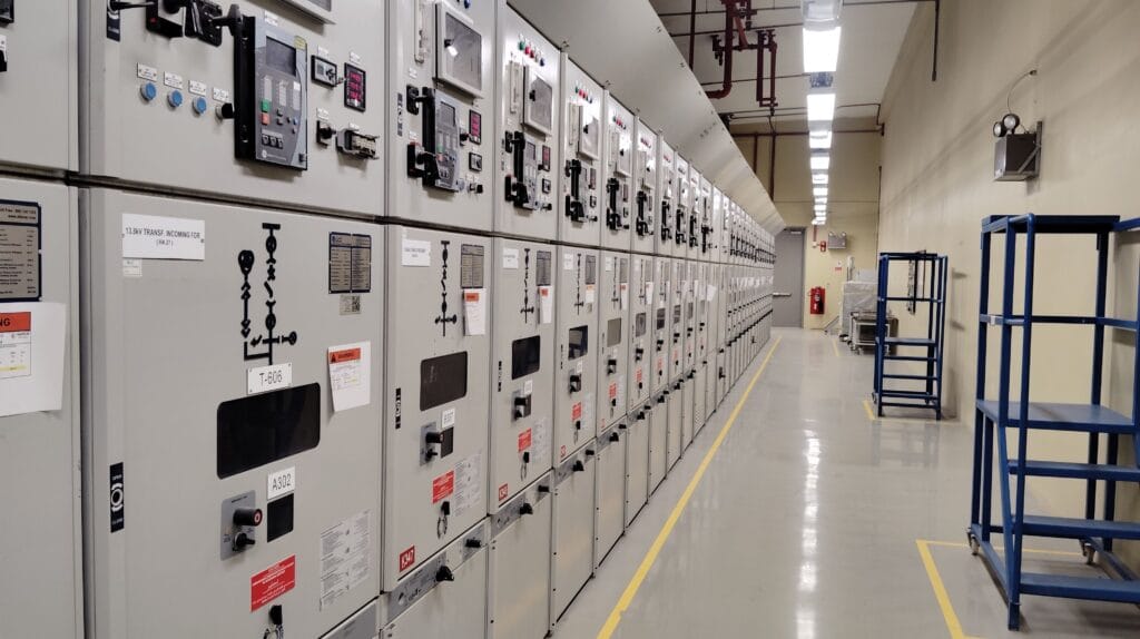
That was the situation on an industrial solar installation in Morocco. A SEPAM protection relay, configured for residual voltage detection — the V0 earth fault function — was tripping repeatedly throughout the day. Each trip meant a production stop. Each stop meant lost energy, lost revenue, and a maintenance team called back to the same panel, checking the same readings, finding nothing obviously wrong.
This article documents what that fault actually was, how it was diagnosed, and what changed once the right parameter was identified — not guessed at, identified.
Disclosure: This article contains affiliate links. If you purchase through these links, I may earn a small commission at no extra cost to you. I only recommend technical resources that I consider genuinely useful for industrial solar professionals working in Africa and the MENA region.
What the SEPAM V0 Function Actually Protects Against
The SEPAM relay family, widely used in industrial electrical protection schemes including solar PV installations connected to medium-voltage networks, includes a residual voltage protection function commonly referred to as V0 or earth fault voltage protection.
In simple terms: this function monitors for an imbalance in the electrical system that indicates a connection to earth where there should not be one — a ground fault. When the residual voltage exceeds a configured threshold for longer than a configured time delay, the relay trips the breaker to protect equipment and personnel from a potentially dangerous fault condition.
This protection exists for good reason. A genuine earth fault left undetected can damage equipment, create safety hazards, and in some cases lead to fire risk. The V0 function is not the problem. It is doing exactly what it is designed to do.
The problem, in this case, was not the existence of a fault. It was the frequency and pattern of the trips — multiple times per day, on an installation where no actual sustained ground fault condition could be confirmed through physical inspection.
The Diagnostic Process — What We Actually Checked
When a protection relay trips repeatedly without a clearly identifiable hard fault, the instinct of many technical teams is to suspect the relay itself, or worse, to consider replacing it. That instinct is understandable but often misguided — and it is also expensive, both in equipment cost and in downtime during replacement.
Before considering hardware changes, the diagnostic sequence followed a structured approach.
Step one — confirming the trip pattern.
Reviewing the relay’s event log showed the trips occurring at irregular intervals throughout the day, with no clear correlation to a specific time, temperature, or operational event. This ruled out an obvious external trigger like a fixed daily thermal cycle.
Step two — physical inspection of cabling and insulation.
A genuine, sustained ground fault should leave physical evidence — insulation degradation, visible damage, moisture ingress at cable entries. Inspection of the relevant string and inverter connections found no conclusive physical fault.
Step three — reviewing the relay’s configured parameters.
This is where the investigation turned. The V0 threshold itself was set at a standard value — typically in the 10% to 30% range of nominal phase-to-neutral voltage, depending on the network configuration. This threshold was not the issue. The function was paired with a very short time delay — in the order of 100 milliseconds — before tripping once that residual voltage threshold was exceeded.
Step four — correlating with known transient phenomena.
Industrial solar installations, particularly those with multiple inverters switching simultaneously or operating near capacitive elements in the system, can generate brief, transient residual voltage spikes that exceed a protection threshold for a very short duration — without representing an actual sustained earth fault. These transients can result from switching operations, inverter commutation, or momentary system imbalances that resolve themselves within milliseconds.
A time delay of 100 milliseconds was simply too short to distinguish between a genuine, sustained earth fault and a brief transient event. The relay was doing its job correctly according to its settings — it just was not given enough time to tell the difference between a real fault and a harmless spike.
The Parameter Change — And Why It Worked
Based on this diagnosis, the time delay setting on the V0 protection function was increased from approximately 100 milliseconds to 200 milliseconds.
This is a deliberate and carefully considered adjustment, not an arbitrary one. The principle behind protection relay coordination is straightforward: the time delay must be long enough to avoid tripping on harmless transient events, while remaining short enough to react quickly to a genuine, sustained fault that requires immediate disconnection for safety.
Doubling the delay from 100 to 200 milliseconds gave the relay enough additional time to distinguish a transient voltage spike — which resolves within a few dozen milliseconds — from an actual sustained earth fault, which persists well beyond that window.
After increasing the time delay from 100 ms to 200 ms, the number of unplanned shutdowns decreased significantly — both on a daily and monthly basis.
This result raised a natural follow-up question: could the delay be fine-tuned further, balancing trip reduction against response speed even more precisely? That question deserves its own dedicated analysis, and it is one we will return to in a future article. For now, the immediate priority was restoring operational stability, and a 200 ms delay achieved that.
Why This Matters Beyond a Single Site
This is not a story about one relay on one installation. It is a pattern that repeats across industrial solar sites wherever protection relays are configured with default or overly conservative time delay settings that were never validated against the specific electrical characteristics of the installation.
Default factory settings on protection relays are designed to be safe across a wide range of installation types. They are not necessarily optimized for any specific site’s actual transient behavior. An installation with multiple string inverters, long cable runs, or specific grounding configurations may generate transient residual voltage events that a generic default setting interprets as faults.
This connects to a recurring theme on this blog: monitoring systems excel at recording what happened, but rarely explain why. The relay log told us when trips occurred. It took physical inspection and electrical reasoning — not software — to understand why.
The financial impact of this kind of nuisance tripping is rarely discussed in feasibility studies or commissioning documentation, but it is real. On a 2 MWp installation generating approximately 360,000 USD per year, each 15-minute outage during peak production hours represents an estimated 10 to 20 USD in lost generation value. At 3 trips per day, that is roughly 30 to 60 USD lost daily — and 900 to 1,800 USD per month — before accounting for the maintenance time spent investigating each event, the cumulative wear on switching equipment from repeated operation, and the operational distraction of a recurring issue that never quite gets resolved.
None of this appears as a distinct line item in any financial report. It simply erodes performance quietly, month after month, until someone takes the time to investigate the pattern rather than just resetting the breaker.
The Broader Lesson — Protection Settings Deserve the Same Scrutiny as Performance Data
Most of the operational issues documented on this blog — soiling, thermal derating, string losses — relate directly to energy yield. This case is different. It is a reminder that protection and control system settings deserve the same level of scrutiny and site-specific validation as the panels, inverters, and physical infrastructure.
A protection relay that is too sensitive costs you production through nuisance tripping. A protection relay that is not sensitive enough creates a genuine safety and equipment risk by failing to react to a real fault in time. Getting this balance right requires understanding the actual electrical behavior of your specific installation — not simply accepting factory defaults or generic engineering guidelines.
This case is also a reminder that protection settings on an industrial site are rarely isolated decisions. The V0 time delay interacts with upstream and downstream protection devices across the electrical network. A change at one level should always be checked against the overall protection coordination scheme, not adjusted in isolation.
For engineers and technical directors who want to build a deeper, rigorous understanding of protection relay coordination, fault current behavior, and earth fault detection principles in industrial electrical systems, Protective Relaying: Principles and Applications by J. Lewis Blackburn and Thomas J. Domin remains one of the most authoritative references in the field. It covers the theoretical and practical foundations of protection coordination — including residual voltage and earth fault protection — with the depth needed to make informed, site-specific parameter decisions rather than relying on default settings alone.
This is the kind of reference that earns its place on a technical director’s desk — not for casual reading, but for the moments when a parameter decision actually matters and needs to be defensible.
What I Would Tell Any Engineer Facing This Exact Situation
Do not jump to replacing the relay. A repeatedly tripping protection function is far more often a configuration and coordination issue than a hardware failure. Replacing working equipment based on a misdiagnosis is an expensive and entirely avoidable mistake.
Start with the event log. The pattern of trips — their timing, frequency, and any correlation with operational events — tells you more than any single trip in isolation.
Inspect physically before adjusting parameters. Ruling out a genuine, sustained fault through inspection is a necessary step before deciding that a setting adjustment is the right path forward. Adjusting a time delay to mask a real fault would be a serious safety mistake.
And when you do adjust a time delay, understand the trade-off you are making. Every additional millisecond of delay is a trade between nuisance trip reduction and response speed to a genuine fault. This is not a setting to adjust casually — it deserves the same rigor as any other safety-critical engineering decision.
A relay that trips 2 to 4 times a day is not a mystery that requires new equipment. In this case, it required asking the right question: was this relay seeing a real, sustained fault — or was it reacting too quickly to something that resolved itself in milliseconds?
The answer came from the event log, from physical inspection, and from a careful, deliberate adjustment to a single parameter — increasing a time delay from 100 to 200 milliseconds. The result was a measurable, significant reduction in unplanned shutdowns, both daily and monthly.
This is the kind of fix that never appears in a project’s marketing materials and rarely makes it into a feasibility study. It is also exactly the kind of fix that protects an installation’s real-world performance — quietly, technically, and without fanfare.
If your installation is experiencing repeated, unexplained protection trips, the equipment is very likely not the problem. The configuration almost always is.
Looking for verified data?
The field insights behind this article are fully documented in the MENA Industrial Solar Data Guide. Get access to real project costs, actual KPIs, and genuine O&M benchmarks from a live industrial installation in the MENA region.
👉📘 75 pages of pure field data. Zero simulations.
👉 Get the Guide — $29 USD
Get the Free Preview
The first 8 pages of the MENA Industrial Solar Data Guide — real Performance Ratio data, soiling measurements, and thermal derating figures from an industrial installation— No spam, just real data.
Disclosure: This article contains affiliate links. If you purchase through these links, I may earn a small commission at no extra cost to you. I only recommend technical resources that I consider genuinely useful for industrial solar professionals working in Africa and the MENA region.
Publié par :
Solar PV MENA Expert